Overview
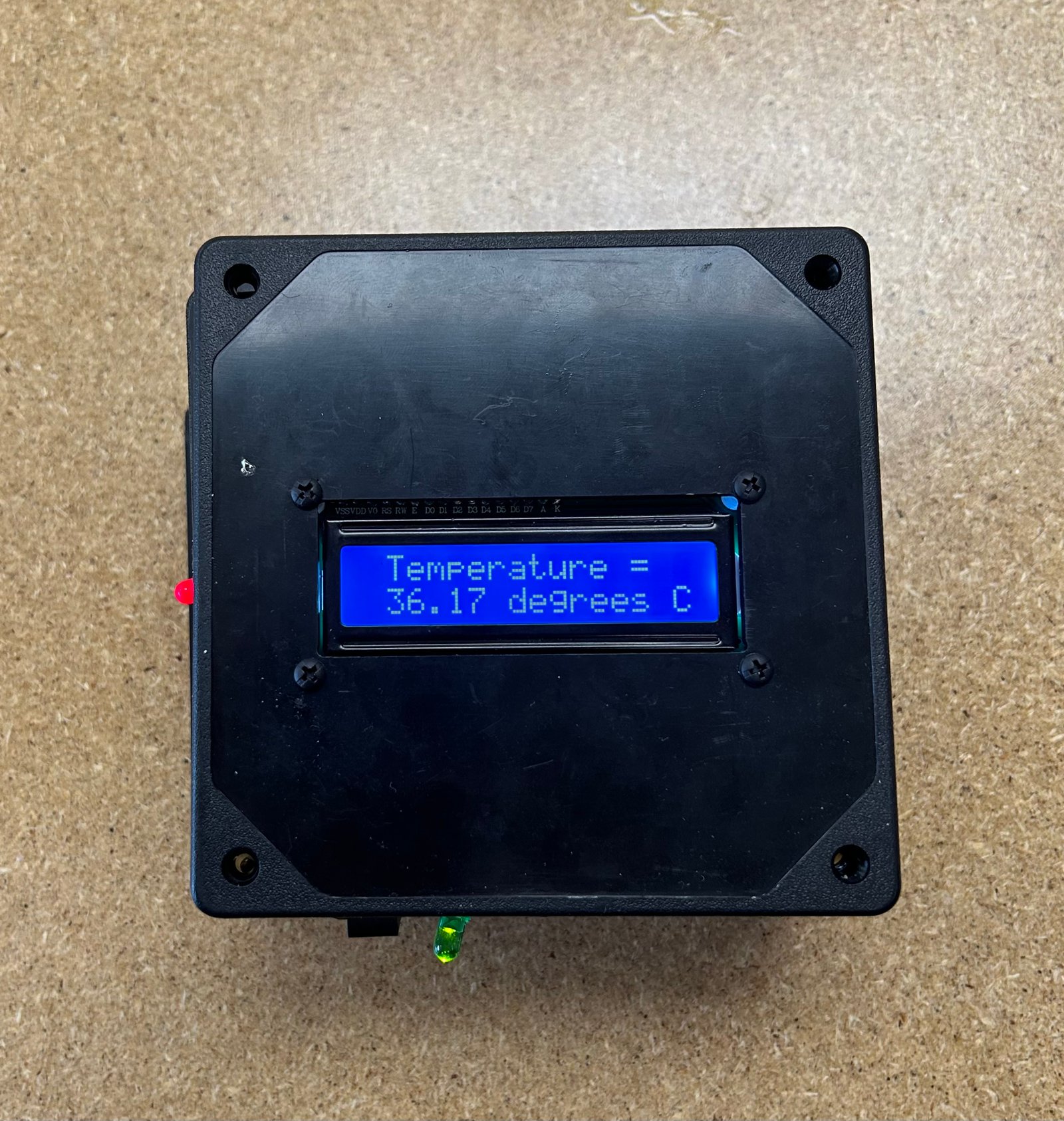
The EK131 final project involved building a temperature sensor box that triggers an alarm and illuminates an LED in different colors depending on whether the temperature is inside or outside a set range. The goal was to combine the semester’s hands-on toolkit—sketching, drill pressing, laser engraving, 3D printing, and soldering—into one polished build that’s reliable and demo-ready.
What it does
Reads temperature → compares to thresholds → sets RGB LED state + buzzer alert.
Engineering focus
Wiring discipline and solid solder joints so sensor readings stay stable and repeatable.
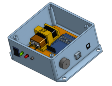
Build
The enclosure was assembled with durability and organization in mind: routed wiring, strain relief, and clean separation of power/ground from signal wiring to reduce intermittent behavior.
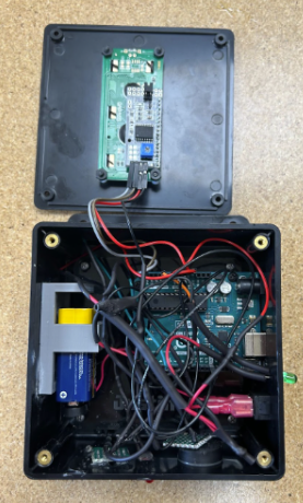
Electronics
The electronics combine sensing and feedback: a temperature sensor input, an RGB LED output, and a buzzer alarm output. Debugging centered on identifying weak connections and reducing noise-related reading instability.
Inputs
Temperature sensor signal converted into a temperature value in firmware.
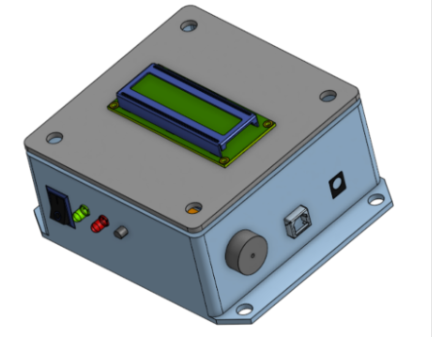
Outputs
RGB LED status + buzzer alarm when temperature crosses thresholds.
Fun Feature
The buzzer doesn’t just beep—it plays the Harry Potter theme. I integrated a melody routine so the device still behaves like a real alert system, but feels personal and demo-friendly.
Why it works
Memorable demos while still clearly signaling an “alarm state.”
Engineering angle
Timing and state transitions matter so audio doesn’t glitch or block sensing.
Results
The final build reliably triggers LED state changes and an audible alarm when thresholds are crossed. The biggest takeaway was how wiring quality and noise can directly affect sensor accuracy—and how to debug systematically with a multimeter and cleaner connections.
What worked best
Multimeter validation + rework of weak solder joints improved stability.
Big takeaway
Signal reliability starts with mechanical robustness and wiring discipline.
Reflection
Challenges
• Organizing solid-core wiring inside the enclosure
• Finding weak joints after heat-shrink and reworking cleanly
• Stabilizing readings when voltage connections were noisy
• Handling fragile components during assembly
What I learned
• Converting voltage/sensor readings into temperature in code
• Better soldering + connectivity practices
• Using Onshape for mechanical planning
 by Justin Yu