Overview
The goal of this project was to design and optimize a 2D truss that could support a required load while staying within strict geometry, material, and cost constraints. Instead of doing repeated method-of-joints calculations by hand, we built a MATLAB workflow that solves member forces via a single global equilibrium system, then predicts the maximum supported load by checking compression members for buckling. With fast analysis, we iterated designs quickly and made decisions based on load-to-cost efficiency.
What I built
A parameterized truss solver: input geometry → assemble equilibrium matrix → solve member forces + reactions → buckling-limited max load → cost + ranking.
Why it matters
Truss design is all about iteration. Automating analysis makes it realistic to compare many candidates and converge on a strong, efficient structure.
Approach
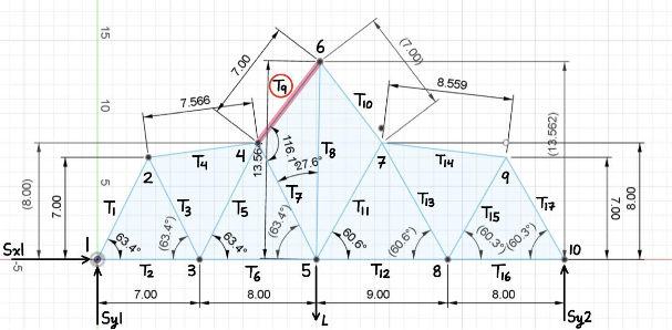
We structured the tool around a clean “input → solve → evaluate” loop so trying a new truss was as simple as updating a geometry definition. Each candidate is defined by joint coordinates, member connectivity, supports, and an applied load case. The solver returns the full force state (member forces + support reactions), then a post-pass evaluates buckling capacity and cost.
Inputs
Joint coordinates, connectivity, support conditions, and load application point.
Outputs
Member forces, T/C classification, reactions, critical buckling member, max load estimate, and cost metrics.
Modeling
The core of the solver is a global equilibrium system built from the truss geometry. For each member, we compute its length and direction cosines, then populate the x/y force-balance rows for the member’s connected joints. Support reactions are appended as additional unknowns. Solving the assembled linear system yields member forces and reactions in one shot. A separate failure check focuses on compressive members and uses buckling behavior to estimate the maximum supported load.
Optimization
Once each candidate design is solved, we evaluate two things: (1) the predicted maximum load before buckling and (2) a cost model based on joint count and total member length. This makes it possible to compare designs objectively using a load-to-cost ratio. In practice, the strongest designs weren’t always the best — small geometry changes that shortened vulnerable compression members often improved capacity while also reducing material cost.
Buckling-driven design
Compression members dominate failure. Reducing their effective length is often higher leverage than “adding more members everywhere.”
Decision metric
We ranked candidates with load-to-cost efficiency so the final design was strong and economical.
Results
With analysis automated, we tested multiple geometries quickly and converged toward a design that balanced strength and cost efficiency. The solver identified the most critical compression member in each candidate and predicted the buckling-limited maximum load, which helped target the highest-impact geometry changes during iteration.
What worked
Turning geometry into a repeatable solve made iteration fast and comparisons fair.
What mattered most
Shortening high-compression members improved buckling capacity without excessive added cost.
Preliminary Design Report
Embedded PDF viewer below. If it doesn’t load, use the “Open PDF” button.
If your browser blocks embedded PDFs, open it in a new tab: Open PDF
Reflection
Challenges
• Keeping sign conventions consistent during equilibrium assembly
• Handling edge cases (near-zero forces, geometry tweaks) without breaking outputs
• Designing for buckling constraints instead of only “overall stiffness”
What I learned
• Global statics as a linear system (fast + scalable)
• Buckling-first thinking for compression members
• Ranking designs with metrics (load-to-cost) for real trade studies
 by Justin Yu